DIY LED Hula Hoop
Bill of materials
-
3 meters of Adafruit Digitally Addressable LEDs or any 5V strip with LPD8806 chips
-
4 14500 900mAh Lithium batteries with tabs
-
3-4 meters of 1” HDPE (High-Density Polyethylene) tubing
-
3 resistors (doesn’t really matter which, any will do)
-
a bunch of wire.
-
Bubble wrap
So I made an LED hula hoop. It has 96 LEDs, 105 different modes, and lasts about 3.5 hours at full brightness. It’s also the only hoop I’ve seen that displays a message using persistence of vision .
Batteries
The batteries are wired in parallel so they basically just add up the mAh capacity. If they were wired up in series, the voltage would add instead. The hoop would work with just one, but then the mass wouldn’t be evenly distributed and the hoop balance would be a little off. And it would also go dead in half an hour. They start out sending 4.2 volts, but slowly drop until it hits 3.3 volts (the actual discharge characteristics depend on the temperature). They are the same size and shape as AA batteries, but keep in mind, AA batteries are 1.5v, and these are not.
The batteries are wired up behind a Tenergy 32003 to protect them from overdraining and overcharging. When in use, the hoop will actually cut off before the voltage goes too low to prevent damage to the batteries. The circuit protects from overcharging too, but so does the charger. The 32003 didn’t want any more than 4.2 volts, so finding a wall-wart charger was a little difficult. I ended up wiring a charger directly into an extra charger for 18650s . It only charges at 600 mA, so I’m sure there’s a more appropriate charger out there.
LEDs
The LEDs operate on a daisy chained controller, and come printed on a pretty flexible strip. 5050 RGB LEDs are mounted about every 2.5 inches. The LEDs are rated at 5 volts, but will dim when given lower voltage. I was actually able to overcharge them and get them brighter, but was warned this would burn the drivers if I kept at it so I stopped. My original plan was actually to run on 7.4 volts to keep them this bright.
Arduino
At Bonnaroo 2010 , I met this guy who had built his girlfriend a hoop, and was a huge help in this one. He pointed out that the Pro Mini can run off of anywhere from 3 volts to 5 volts. The difference is really just the crystal operating at 8 or 16 mHz (for stability concerns). So that made things a lot simpler.
The LED strip has two inputs for power, and two wires going to the Arduino for data and clock. The library that Adafruit provides for it lets us use any two pins on the Arduino to control it via bit-banged software SPI. However, if you happen to have pins 11 and 13 free (which we do), then you can use hardware SPI and get roughly 3-4 times the speed which makes POV at high speeds (i.e. while hooping) possible. If you edit the source of the LPD8806 library, you can change the SPI clock divider to go even faster, but you’ll have to worry about interference.
I used pins 2, 3, and 4 for pushbutton switches. 4 can be moved around, but 2 and 3 were pretty important because I send the arduino its sleep mode to save power. External interrupts pull it out and wake it up, but only pins 2 and 3 can do this.
So basically there’s an “off” button, a “mode” button, and a “color” button. The modes cycle through various modes of “Solid”, “Dragonfly”, “Strobe”, “Chasers”, “Chasers with statics”, “Rainbow”, and POV. The colors cycle through various colors, except for the chasers, where you can cycle through all the colors, and keep cycling through adding another chaser every time, up to 5. The POV mode displays the logo of Carrot Creative . Space is pretty cramped on the chip, so it’s just stored as an on/off bitmask, 32 pixels high (so each column is 1 32-bit int). The first few columns are green, so I just did that bit manually.
Assembly
Probably the most frustrating part of this project is the assembly. It’s important for everything to be snug inside of the hoop so it doesn’t rattle, and wrapping it in bubble wrap greatly helps this, but the bubble wrap grips the sides of the tube. Taping three unraveled coat hangers together, and using them to pull the strip through helped a lot. Another thing to watch out for is that the contacts need to be insulated and wrapped in electrical tape so you don’t get shorts inside the tube which are nearly impossible to find and fix without a complete disassembly.
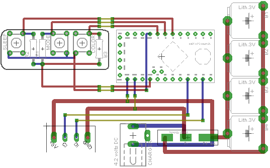
Source Code & EAGLE Wiring Diagrams
UPDATE, 2012-09-28: Here’s how I turned an image into a bitmask for the POV
UPDATE, 2014-05-08: A note about the tabs, it’s important to get a battery with tabs. We’re soldering our wires directly to the battery tabs that are arc-welded to the battery itself. You never want to solder directly onto the battery itself because you will either have a bad solder joint which will break off later, or you will heat up the battery so much during soldering that it explodes. That’s bad.
UPDATE, 2018-08-17: You can get batteries with the protection circuit built-in. That should simplify things.